
By way of background, some 15 or so years ago I rebuilt my Quad 57’s using Rob’s kit – yes, Rob has been providing rebuild kits for a long time! The 57’s have been in storage for a few years, and I pulled them out recently and they are still sounding as good now as they did after their rebuild – a credit to Rob’s materials and guidance.
My 63’s were manufactured in the late 1980’s and had sequential serial numbers. I don’t know their history really – I purchased them about 9 years ago from a collector as being ‘in need of attention’. One clicked regularly and was a bit lower volume-wise. The other was pretty quiet, but both sounded somewhat flat and dull compared to my lovely Quad 57’s – they lacked the magical transparency I thought an electrostatic should display.
So, the 63’s have been on the books for a rebuild for quite a few years, but the opportunity hasn’t arisen until recently.
On disassembly, I discovered one 63 that looked largely untouched, but missing quite a few screws in the base suggesting that someone had been inside at some stage. All panels had what looked to be original serial numbers. It had a late style EHT board. On disassembly the diaphragms on all panels were nominally intact, but on closer inspection all showed signs of the diaphragm debonding from the long edge around the centre, and they had noticeably lower tension in the centre compared to closer to the ends.
The second speaker was a different story. It had clearly been pulled apart, as half the base screws were missing, as well as 5 of the 8 nuts that hold the base to the frame. The ionisation antenna was missing completely, and the EHT board had been replaced with an old style one, and looked to have been poorly rebuilt at some stage with a few spots of PCB track missing. The dust covers were floppy and had various pieces of tape over holes. The serial numbers on the treble panels on this speaker were later than expected, but the base ones looked like original numbers. On disassembly, the base panels looked the same as the first speaker - some debonding on the long edge. The treble panels were quite different – the latest serial number one was completely intact and diaphragm fully bonded, but it had significant excess diaphragm glue squeezed into the panel, also excess glue holding the stators in place. The other treble panel was a slightly earlier serial number than the first treble panel and on disassembly the diaphragm literally fell off, completely intact - despite being a later serial number than the base panels and presumably manufactured later, it was by far the worst of all the panels. Despite one treble diaphragm being intact, I decided to do both treble panels so that they matched.
None of my stators had detached from more than one or two cells – so I could re-glue them in place. The loose diaphragms, but stators still attached, probably explains why the speakers still worked, but didn’t sound that great.
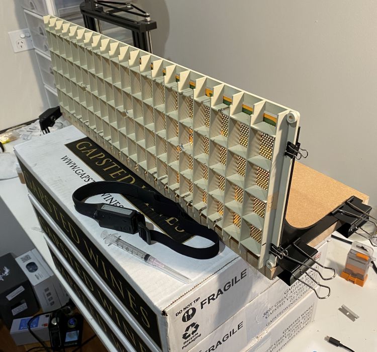
Rebuilding the panels was slow, but not difficult. Since I didn’t have any stators loose, I had 16 that needed to have fillets added as preventative maintenance. I decided to 3D print some stands so I could do the panels on their side, and sat them on some wine boxes (I seem to have acquired a few of these during COVID….) so I could sit and do them comfortably at eye level. I used a $12 LED headlight purchased off eBay, which made a big difference. Rather than use a small brush to apply the glue, I found a 3ml syringe and an 18g drawing-up needle useful – the drawing up needle is blunt, and a good size to slowly dispense the glue. And the 3ml syringe was right – each panel side only required 2-2.5ml and the syringe enabled me to achieve a suitable gradual flow of glue. Whilst I was fortunate that I didn’t have any stators so debonded that they needed to be separated completely and re-glued back on, the trade-off was that it took a long time to work along each side of the grid of each panel (so 16 in total) adding glue fillets – it took about 45 minutes per panel side, taking care to only add sufficient glue to reinforce the bond, but not so much that it ran and blocked stator holes.
Stretching and bonding the diaphragms went well. I used some unidirectional glass-reinforced packaging tape on a piece of glass (the same piece of glass I used for the 57’s years ago…) to stretch the new diaphragm, and I did a pair of panels at a time. The tape certainly stuck well – given how difficult it was to remove it after I had done a pair of panels I doubt it moved at all whilst the glue was drying. I used plenty of weight (more wine boxes) and the ~2mm wide bead of glue I had used around the edge proved to be spot on. The only challenge I had was ensuring the panels didn’t slide off the masking tape underneath the Mylar when first put in place – they seemed determined to creep a bit as I pushed them down but could be gently slide back into position without harming the stretched diaphragm. I put the wine boxes across both panels which seemed to stop further creep.
Rebuilding both EHT boards was straight forward. Since I had purchased from Rob the components for the late style EHT boards, I changed the circuit on the old style board slightly to match the later style circuit – a minor change.
The black alloy grills needed a bit of attention – a few dents to remove and straightening at the bottom where they had spread and slipped down over the plastic lower frame.
Other parts of the rebuild included new foam pretty much everywhere, sanding and refinishing the timber, repainting the black alloy parts after removing dried out glue, and some Cardas speaker terminals. I also installed updated input board / spark detectors, and added the later model clamp boards, both of which I had purchased from One Thing Audio some years ago when the project first started. And finally, I put in Panasonic MKP capacitors and a film resistor to replace the old input electrolytic cap and stock resistor – I have no idea if these really made a difference…..
The old socks were brown and faded in places and had a couple of holes in them, so I decided to replace them with new black ones. Making new socks proved to be about the hardest part of the rebuild – sewing the lovely light stretchy black grill cloth Rob provided was a challenge for someone that has never sewn anything…. I tried on an old sewing machine I had but, whilst it sewed happily on normal cloth, it didn’t sew the light, stretchy grill cloth at all. Eventually I borrowed an ‘overlocker’ machine and that did it with ease, once I learnt how to drive it and thread the 4 pieces of thread it uses….
I did one speaker first, and then started on the second one. Whilst each speaker sounded great when tested individually after each had been rebuilt, I was initially a bit disappointed when I fired them up in stereo – there was a substantial difference in sound quality and volume between the two speakers. I then remembered that Rob had said the mylar diaphragm ‘relaxes’ a bit and, given that one speaker had been finished for about 3 weeks and one just finished for a day or two, I decided to give them a week or two to settle. Indeed, after a week or two they were pretty much indistinguishable from each other in terms of sound.
At the end of it all, the speakers worked superbly – as I always thought they should.
Overall, for those who are DIY inclined, rebuilding the 63’s was not difficult, but required care, attention to detail, somewhere to keep all the various parts, and plenty of time and patience.
The 63’s are relatively modern in comparison to the 57’s, and were much easier to work on as a result. If your 63’s are in need of some TLC, then I recommend having a go yourself. It doesn’t really make sense to pay for someone else to restore them as the amount of time involved to rebuild the panels, or the cost of replacement panels, makes it a dubious investment. In contrast, the cost of the parts to do it yourself is pretty modest. Rob’s well sorted kit, detailed instructions and his ready support are invaluable. Don’t even think of trying to track down the various components yourself – even if you could, it would probably cost you more, and Rob’s instructions and help are pretty much essential to completing the job and getting a good result.
Thanks Rob!
Dave
 |
 |
|
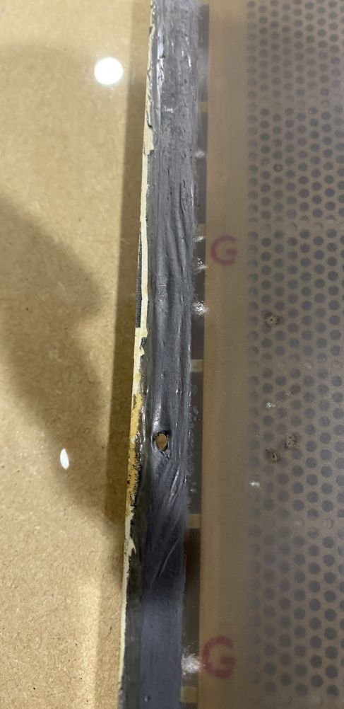
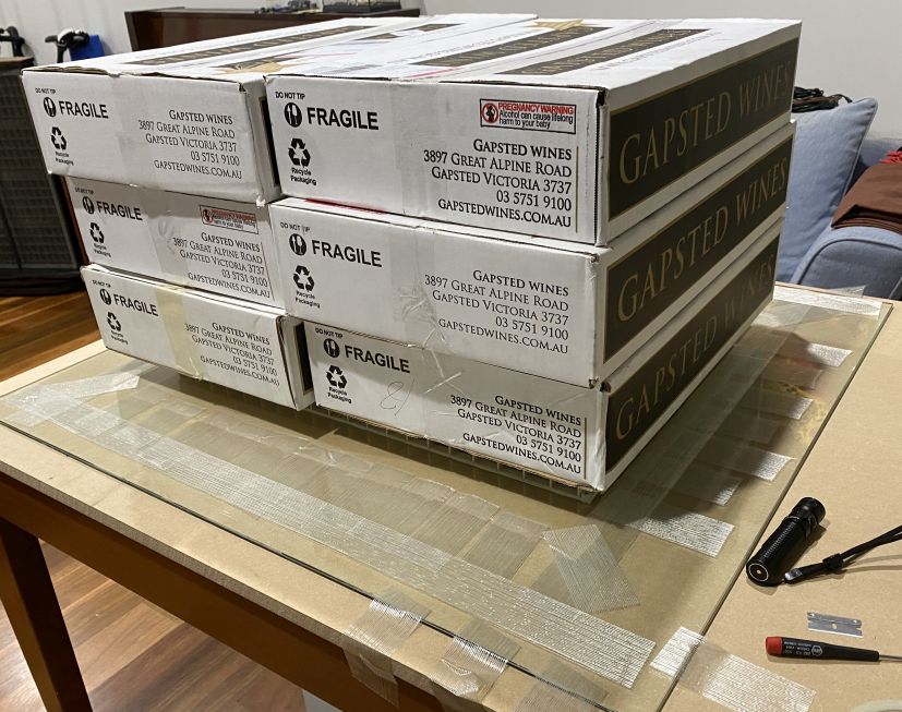
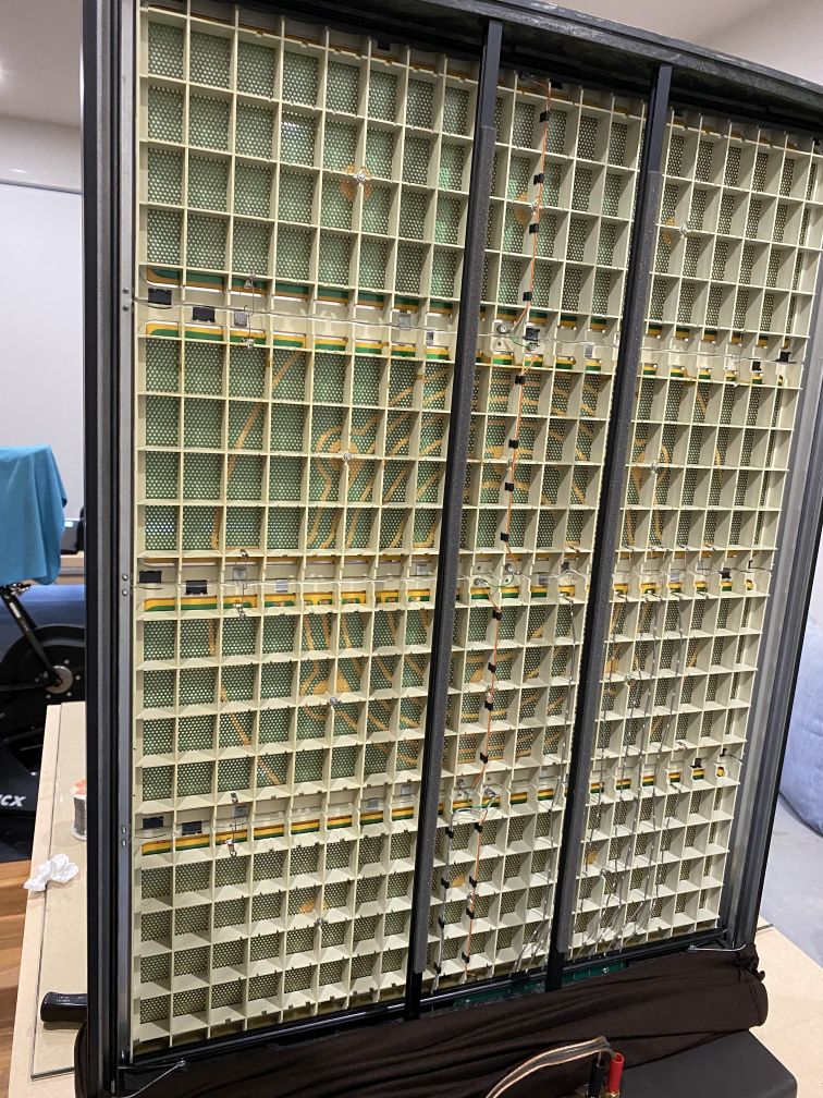
Above left, the original diaphragm has come away from the surface of the air gap spacer causing loss of tension and instability causing clicks and pops etc. Above right, a new diaphragm has been tensioned on a sheet of glass and the panel is currently under pressure (wine boxes) while the glue cures. |
|
 |
 |
|
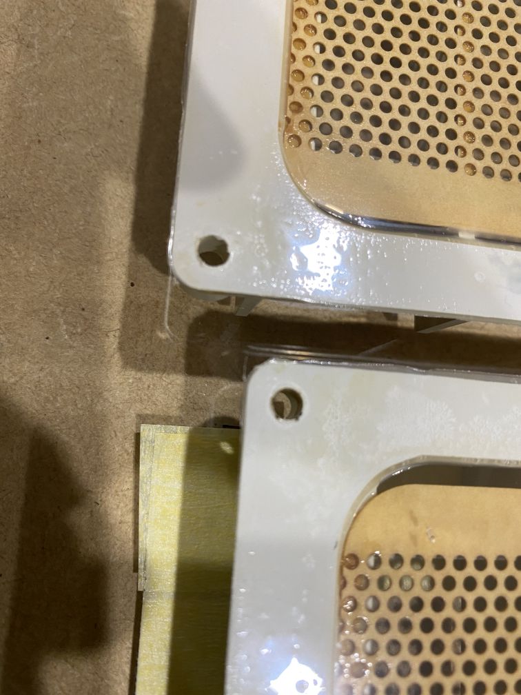
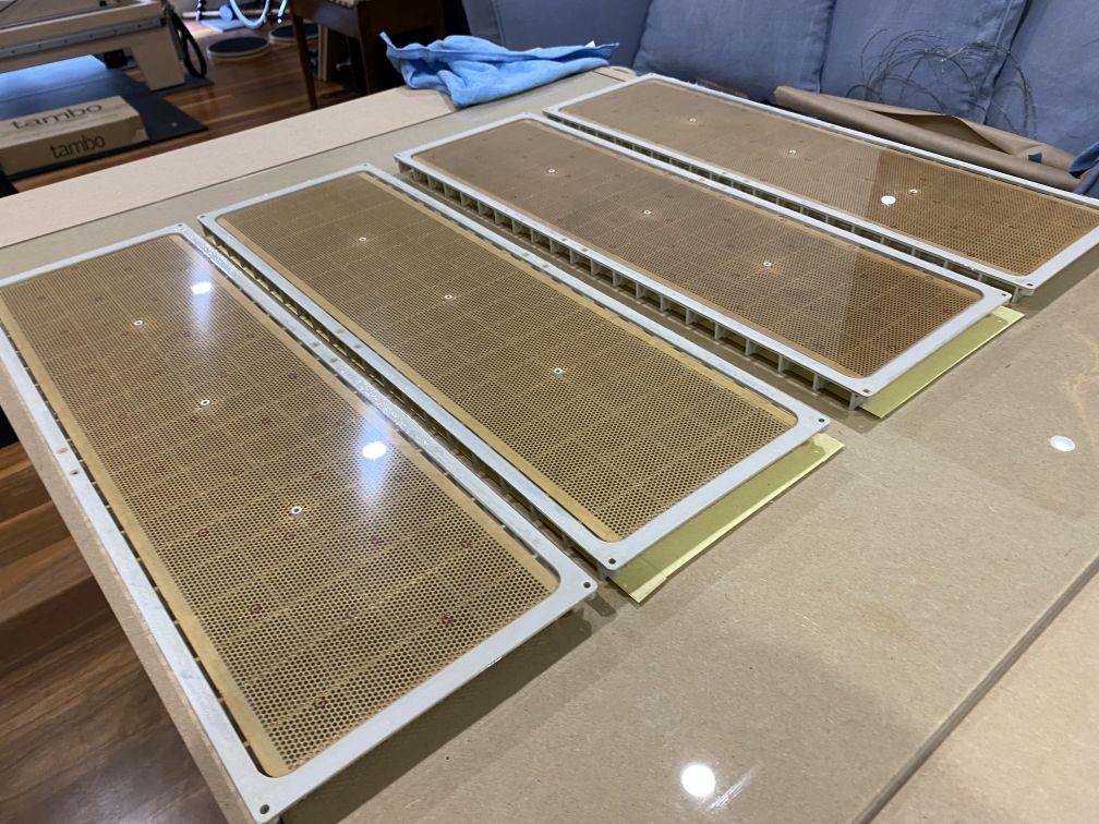
Above left, a close up shot of the bonded diaphragm and glue line. Above right, the four completed panels ready for coating and installation into the speaker frame. |
|
 |
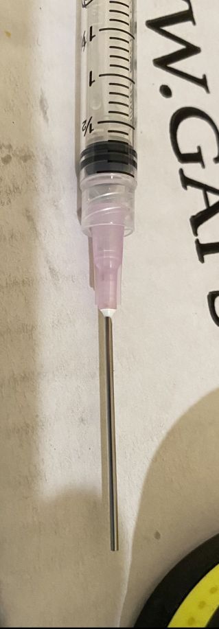 |
| Above, the tools required to carry out some preventative maintenance. This is done to prevent panels that are currently good failing in the near future. The existing glue lines that bond the stator to the support matrix are reinforced with adhesive. It is very important that glue is not allowed to run through the holes into the works. Equally it is important not to allow the gauze that is fitted to the rear panel, soak up too much adhesive, this will clog it and over damp the panel. | |
 |
 |
|
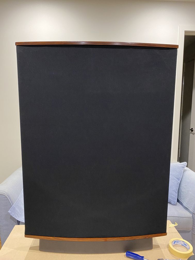
Above, the assembled and finished speaker. The pictures speak for themselves in this case.
Thanks for the update and information on this rebuild Dave, it is much appreciated Rob |
|