
Caution!
As with all Electrostatic loudspeakers, very high voltages are required for normal operation of these panels. Extreme care should be taken when working on the speakers, as contact with the secondary side of the audio transformer under signal conditions can be fatal.
The red resistor in the lower left corner is the high voltage feed to the diaphragm; avoid contact with this component and any others on this side of the board. The underside of the board has high voltages expressed across it; avoid contact with any of the solder pads when the board is powered.
When working on the panels always have the power disconnected and earth the HV Bias wire to ground or one of the stator wires, this will discharge any stored charge in the supply making it safe to handle.
If it is absolutely necessary to have the panels powered to conduct some tests, ensure that all polarising voltage and audio signal wiring is identified before proceeding.
Always take precautions against electric shocks such as only using one hand in the cabinet at a time.
It is assumed that the user possesses reasonable handyman skills. Whilst knowledge of electronics or access to test equipment is not necessary within the scope of this kit, some faults will require specialised skills or equipment to trace.
ER Audio Pty Ltd will guide the user to the best of their ability but can take no responsibility for any damage or injury as a consequence of using this product.
Read through all of these user notes to ensure you are aware of what you can and cannot do when using these panels.
Important
The panels have been supplied with a protective film wrapping, this is to prevent foreign material entering the active part of the panel while in transit and being handled. It’s best to leave the panels wrapped until you are ready to install them into your project. Make sure wood chips, sawdust, swarf etc. do not enter the panels, this can cause poor performance or damage to the diaphragm.
E R Audio 505 MkII
Mini Panel Wiring
Connecting the wires from the panel to the power supply board
Two plugs and crimp connectors have been provided to terminate the wires from the panel and to allow them to be easily connected to the header connection on the power supply board.
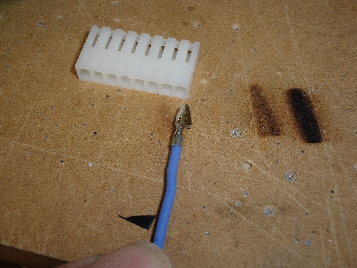
The wires from the panel that are connected to the audio connections should have a crimp connector either crimped or preferably soldered onto the end of the wire. Insert the connector into the plug shell with the barb on the connector lined up with the slot in the shell, this will stop the socket pushing out of the connector shell when it is pushed on to the header.
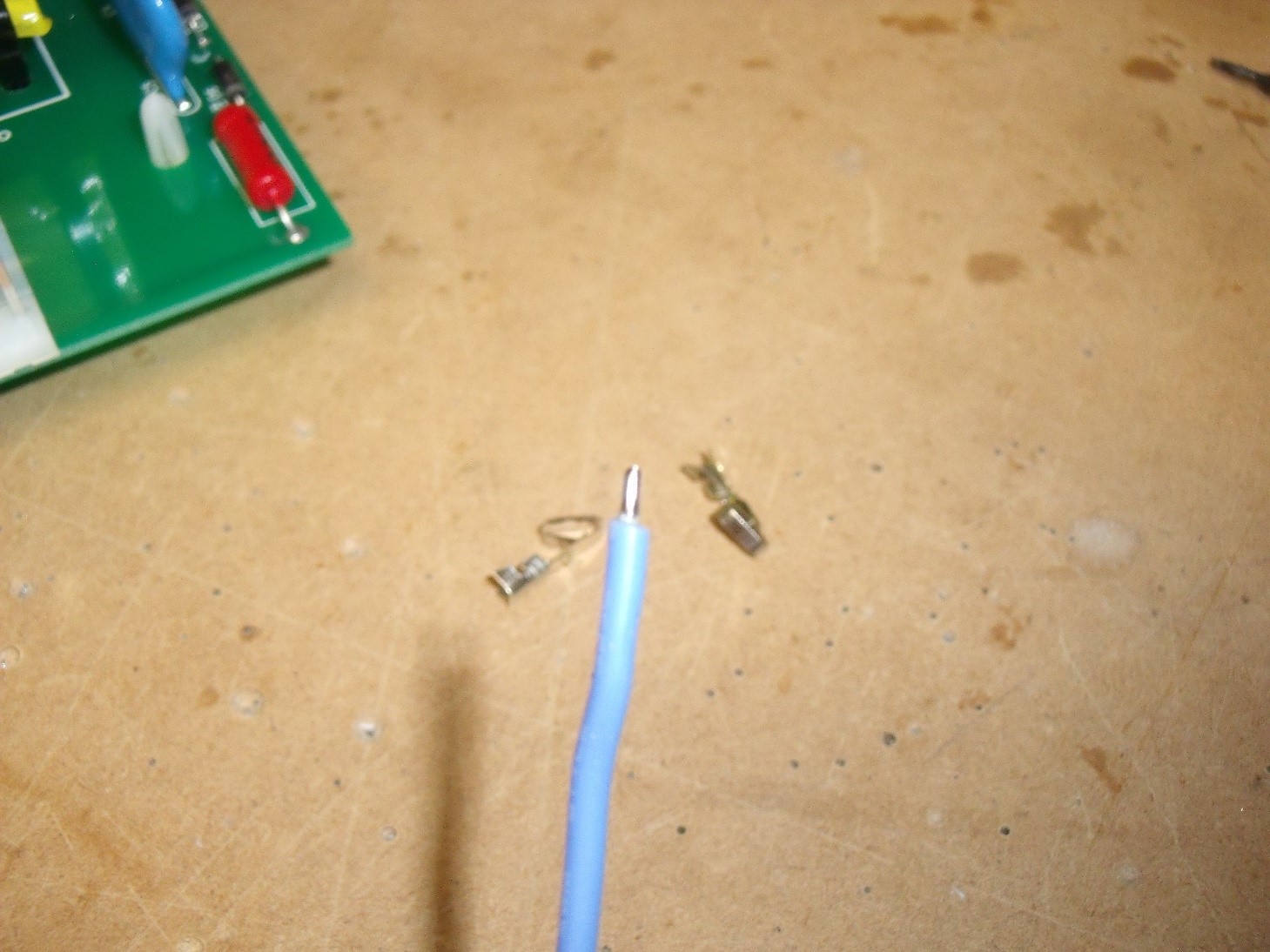
Above, strip about 3 mm of insulation from the wire and tin the exposed conductor with solder.
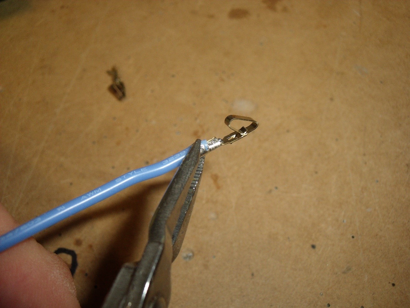
Above and below. Using fine needle nose pliers, or a proper crimper, crimp the terminal onto the wire making sure the
tinned wire is crimped into its seat.
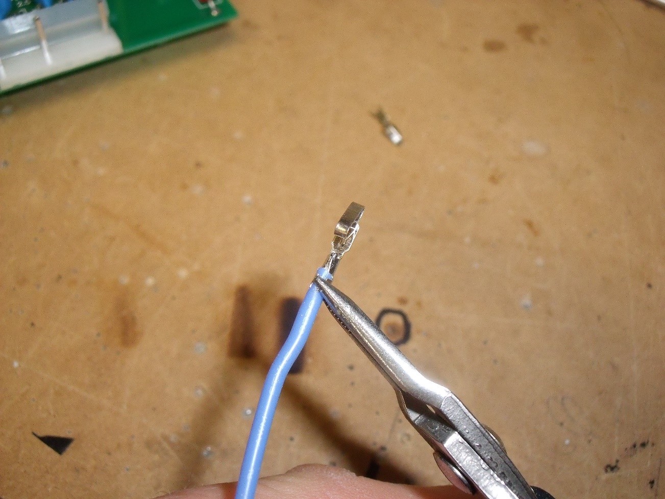
Above, the terminal pin is soldered to the wire. Below, the terminal pin has a barb that stops the pin being pulled from the connector shell. Make sure the pin is inserted into the connector with the barb lining up with the slot in the connector.
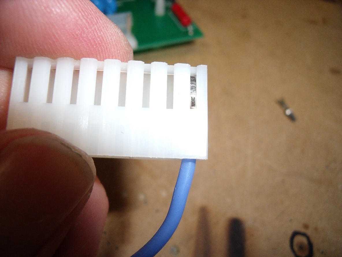
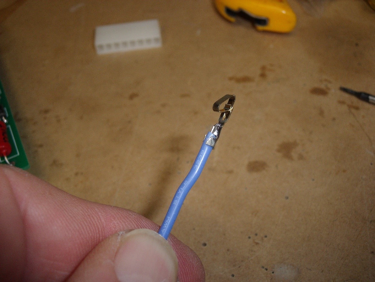
Above, the wire has been inserted into the connector. Below, the same is done with the two other wires to create the connecting cable for the panel. You can see the barb on the connector is in the groove.
Cut the wires to the required length allowing enough slack to give a neat installation.
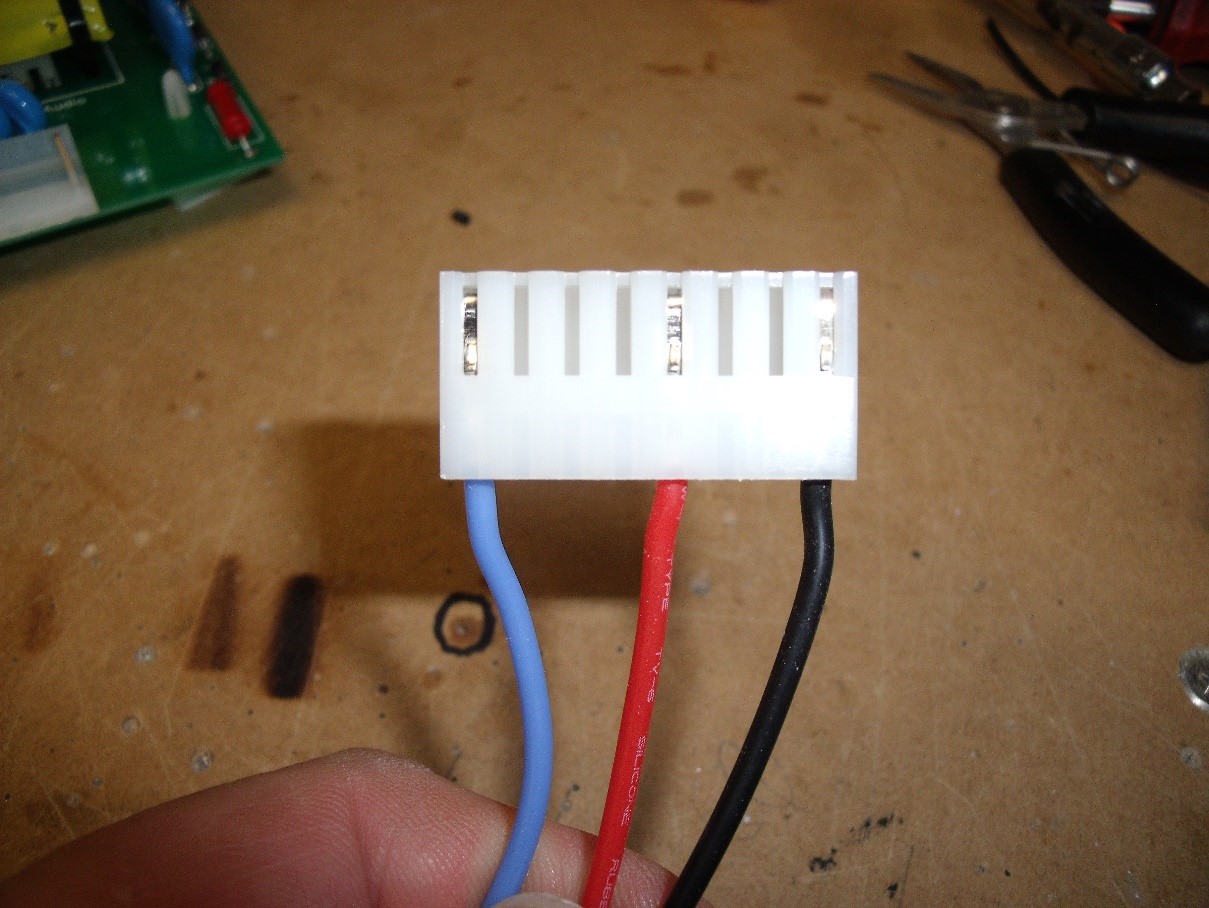

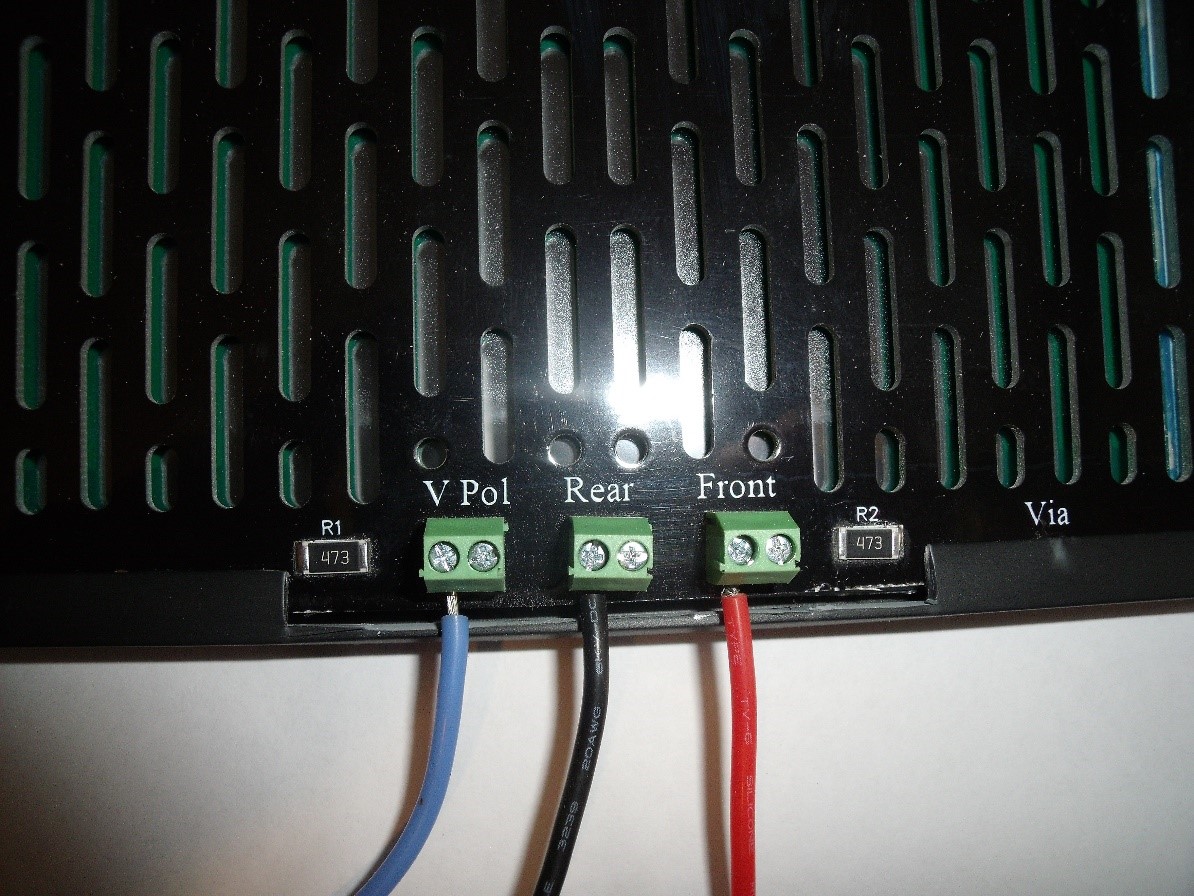
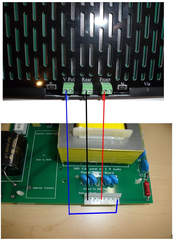
Make sure the wires are connected to the panel as shown in the picture above and below. The colour chosen for each section is not important but keep it the same for both panels to avoid confusion.
Connecting the power supply to the panel
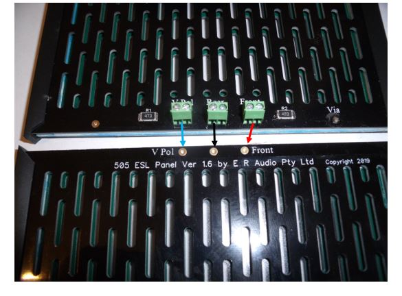
The ER Audio 505 Mini Panels use an electrically segmented electrostatic panel to improve horizontal dispersion and to balance the frequency response. There are three sections, a narrow central strip with a wider strip on either side. These strips run the full height of the panel and are connected to the power supply via the solder pads on the rear of the panel. The front of the panel has the plastic screw heads showing, the rear of the panel has the metal nuts showing.
The 505 panels have been modified to enhance the way electrical connections are made. The older panel had 7 wires connecting the panel to the power supply, this has been changed to 3 wires making connection simpler.
The new panel has surface mounted filter resistors soldered in place that divide the signal when it reaches the panel instead of having the resistors mounted on the power supply. These required separate wires to feed the individual segments of the panel.
The bottom channel section fitted around the edge of the panel is simply clipped in place and taped at the corners. Depending on the type of frame you are installing the panels into you may decide to remove the channel section to allow a better fit.
This is important: If you remove any of the channel section because it interferes with your own enclosure, place some PVC insulation tape over the edge of the panel to avoid high voltage leaking from the exposed edge of the panel to the frame. Ensure the panel halves are held firmly together otherwise charge from the charge rail on the rear stator may not transfer properly to the conductive coating applied to the diaphragm on the front stator.
Above, the connectors for the signal (rear and front stators) and bias supply (V Pol) can be seen here. The surface mounted resistors (SMD) can be seen each side of the green terminals.
Important Note
There are two screw terminals for each connection, it does not matter which terminal is used as they are connected together inside the panel. The two screws and pins entering the stator give greater strength and stability than a single screw and pin.
3 different colours of 6kv rated high voltage wire have been supplied to connect the panel to the power supply. The colour you choose to use for each section is not important, however, it is good practice to keep the colours the same for both speakers.
Strip about 5mm of insulation from the end of a length of HV wire and tin the end with solder. This makes for a good connection inside the screw terminal. Push it into the terminal and tighten the screw at the side. Be very careful when using small screwdrivers on these terminals, a slip may cause the screwdriver to go through one of the acoustic slots creating damage to the diaphragm.
If you have unsteady hands, a sheet of thin cardboard or plastic held in place or taped over the slots may prevent expensive damage.
Do the same with 2 more lengths of different colour wire and connect them to the bias connector and the front stator connector, this is the one by itself on the right-hand side of the rear of the panel.
Panel screws
The plastic screws that hold the panel together in the centre line can stretch over time and may need tightening if slight rattles are heard. The screw thread is fine and is only plastic so be careful that you don’t strip the thread when tightening these screws.
Important safety warning!! If, for whatever reason, you decide to replace the M4 nylon screws that clamp the panel together in the centre for metal ones, be aware that they will become live from their proximity to the charged diaphragm. While this will not affect the performance of the panel there is a danger from electric shock to anyone that contacts a screw head or nut.
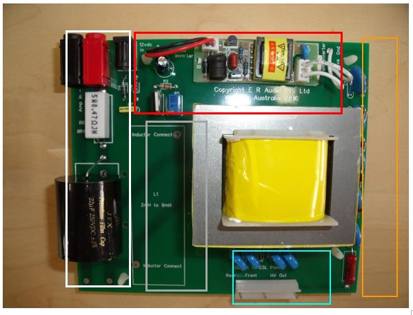
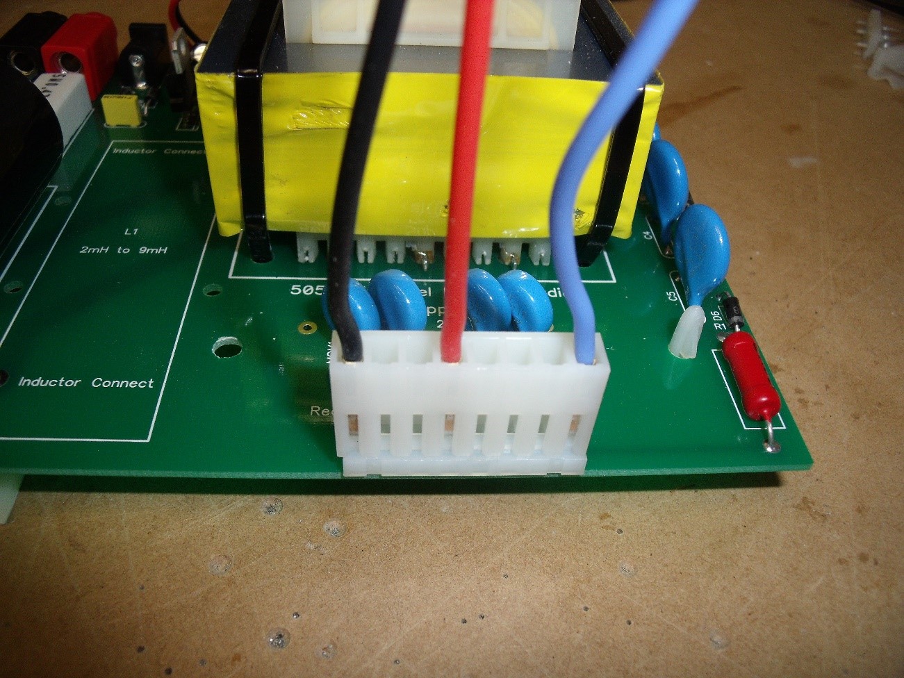
The area in the White box is the input from the amplifier and contains a filter capacitor to filter low frequencies from the panel. There are 2 pads provided for inductor connection, these are located just below the black capacitor in the bottom left of the photograph.
The value of the on-board capacitor is 33uf (note, older 22uF shown above), this value has been chosen to act as a reliable “all purpose” high pass filter, however this will not suit all applications and a change may be desired.
This is important.
The capacitor value can be changed to no more than 82uf, this will allow the panel to operate at its lowest possible frequency, even with this value it will be possible to drive the diaphragm into the stator at high input levels or on music with bass emphasis. If the panel is required to operate at or around 150 Hz we suggest an inductor is used and installed in the space provided. The inductor shunts low frequencies and will steepen the roll off slope from 6dB / octave to 12dB / octave. An inductor value of between 2mH and 9mH will be required depending on the crossover frequency chosen. Use good quality components for best results.
Because the second order filter will change the phase, the panel will need to be connected 180 degrees out of phase with the bass driver to maintain correct phase for both drivers. If in doubt listen to what you have then change the phase of the bass driver and listen to the result. Choose whichever sounds best to you; this will probably be the correct connection.
The filter capacitor may be removed if an active or other crossover is being used. Be aware that driving the panel at frequencies below 150 Hz, even at low levels may cause damage to the panel or saturation of the transformer which will lead to high levels of distortion.
The components in the Red box are for the adjustable voltage regulator and the high voltage inverter.
The voltage regulator takes the 12 volts dc from the mains adaptor and delivers a regulated voltage to the inverter that will not alter regardless of mains voltage fluctuations. The output from the regulator is adjusted with the blue trim pot. In pre-assembled supplies this has been set at the normal voltage required by the panels but can be adjusted to maximise the output after the panels are run in. The initial setting is 7.0 volts measured at the “To Inverter” pads just below the regulator section. You should be able to increase this to 7.5 volts without problems.
Turning the trim pot clockwise increases the voltage applied to the diaphragm inside the panel, conversely, turning it anti clockwise reduces the voltage. If the voltage is too high the panels will hiss or click, the diaphragm could also be pulled over to one of the slotted stators and stick there until power is removed.
Important. Do not adjust the regulator without contacting E R Audio for the correct procedure.
The components in the Light Blue box protect the panel from over driving and provide the connection to the panel.
Note, while the panel is provided with protection from the components on the power supply board, this is designed to protect from short term, high level transients, it is not designed to give protection from sustained over-driving. If the 505 is subjected to long term high level input the protection devices will eventually fail. Protection devices of this type most often fail by presenting a high resistance, tests have shown this to be around 14 kilohms per device. 3 or 4 devices in series with each other will be much the same as the audio transformer driving a 42 to 56 kilohm load. This will cause the output from the panels to be at lower than normal level and there will be some distortion present. This load may cause the 0R47 input resistor to fail.
If the protection devices go open circuit the result may be that the panel is no longer protected and subjected to arcing from stator to stator. Either of the above conditions is undesirable.
If the frequency response of the completed speaker is tested using tones, avoid high level tones for extended periods.
Damage through over-driving is not covered under warranty.
The components in the Orange box create a multiplier that takes the voltage from the inverter and steps it up to a usable voltage required by the panel.
The red resistor at the bottom right is a very high value, high voltage type and limits the current supplied to the diaphragm.
The Grey box is for an iron cored inductor to change the filter to a second order, 12dB/octave type. This inductor is not supplied as standard as we do not know what value you will require to suit whatever bass driver you elect to use. The typical value required will be between 2mH and 9mH.
You may wish to use an air core inductor which will be larger than the space on the board allows, this would have to be mounted off the board.
Mounting the panels in a Frame or Enclosure
There is a myriad of mounting options for the 505 panels, the simplest being a picture frame type of enclosure where the panel mounts in a recess in the frame and is retained by clips or a thin removable inner frame. More complex frames such as those made from glass or clear Perspex will require some other form of mounting and ingenuity.
However, regardless of the type of frame you wish to mount the panels in they all have one thing in common, this is to hold the panel securely without any instability that would allow the speaker to fall over.
The 505 panel is approximately 510mm high, 154mm wide and around 10mm thick. Panels may vary slightly from these dimensions due to some constructional variations.
This is important.When mounting the panel inside a picture frame type mount, make sure that there is around 3mm across the width and 5mm along the height for expansion / contraction of the frame and panel. Do not mount the panel tightly in the frame.
While this may seem like a good way of ensuring the panel is held firmly with no way of moving, it is likely to lead to unexpected instability of the panel. The is usually evident by odd noises such as whining, clicking, popping and hissing.
The panel should be held in a flat plane with no twisting evident, again, instability may follow if this is the case.
Mounting the Power Supply in an Enclosure
The power supply can be mounted in the speaker box or enclosure or can be mounted in a stand-alone box. In all cases the underside of the circuit board has high voltages across it and can arc to any conductive material that is close. If you are mounting the power supply in a metal box add a layer of plastic or other insulator beneath the circuit board, this will isolate the power supply from the metal and prevent arcing.
Curving the Panel for use as a Centre Speaker
It is permissible to apply a gentle curve to the 505 panels along the vertical plane.
When the 505 is used as a centre speaker it is commonly placed horizontally, we recommend 2 panels mounted end to end (horizontally stacked) for the best effect. This will give a 1 metre wide by 150 mm high sound source. Vertical dispersion will be good due to the segmented layout of the panel but you may find it necessary to improve horizontal dispersion depending on the listening position and room size etc.
A gentle curve to the panels can be applied to improve horizontal dispersion. This can be done by routing a 10mm wide slot in the top and bottom plate of the enclosure. The slot should be routed on a radius no smaller than 1.5 metres. A radius that is too tight will change the internal dimensions of the panel and could lead to instability. This would be evident in clicking, popping or hissing noises from the panel.
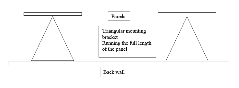
Wall Mounting a 505 Panel
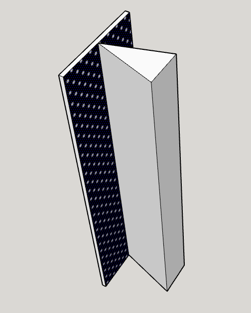
A triangular bracket is required so that the rear sound wave is deflected onto the rear wall at an angle preventing it from being reflected back to the panel and re-radiated. Having a panel close to a wall without dealing with the rear wave will result in muddy sound reproduction. Ideally, the width of the base of the triangle is the same as the width of the panel, 150mm. The panel can be mounted at the apex of the triangle with a single bolt, this will allow the panel to swivel and be angled towards the listening position.
This can be taken further by having one fitting on a screw or slot to enable it to be shortened or lengthened, giving some vertical tilting capability.
Connecting an amplifier to the panel
The input connection to the power supply board from the amplifier is optional, this may be screw terminals for supplies that will be buried inside the bass driver box or banana sockets for externally used power supplies in their own small enclosure. Screw terminals are supplied as standard.
Connect the output from your amplifier to the black and red banana sockets or screw connectors at the top left of the board or to the positive + and negative – screw terminal.
Important
The banana sockets are spaced at the conventional 19 mm between centres. Using large metal banana plugs may cause them to touch each other and short the output from the amplifier. Make sure there is enough clearance between the banana plugs to prevent a short circuit occurring. While some amplifiers will tolerate a short circuit, others will not and can become damaged.
A screw terminal is provided for 12vdc input from the power adaptor. Make sure you get the polarity around the right way. The circuit is protected from incorrect connection but, needless to say, the supply will not work unless it is connected correctly.
A slight rustling or clicking sound may be heard from the panel as it charges, this is normal and will go away after a short time.
Leave the connected panel to fully charge for around 15 to 30 mins before you do any critical listening.
The panel will need to run in before it performs at its best, a couple of weeks normal listening should be sufficient.
Testing
If you plan to check frequency response with tones, be aware that high level tones may trigger the protection or cause transformer saturation. The protection is designed to clamp any short term transients by activating at a pre-set voltage creating a short circuit on the transformer secondary, this will prevent the panel becoming damaged and may cause the protection in your amplifier (if it has such a circuit) to activate. In the event the protection devices are triggered for longer than a short term transient, ie when testing with tones, it is likely the 0R47 ohm resistor on the input will fail, this acts rather like a fuse and protects the transformer from damage. If your amplifier is not fitted with protection be very careful when testing as damage to the amplifier may result.
We strongly suggest you simply run the panels with audio first to run them in and establish a benchmark for performance.
Once the panels are run in you can check the response but do this carefully, we do not warrant the panels or power supply for damage caused by over-driving.
Routine Maintenance
We recommend the use of acoustically transparent grille cloth to prevent entry of dust and insects into the “works”. However, we do understand that there is some cosmetic advantage to having the panels operating without cloth spoiling the “see through” look.
If used without grille cloth, from time to time it may be necessary to remove dust and insects from the panels.
A loss of output or random clicking or popping noises could mean that dust or dead insects are causing a high voltage discharge path.
The solution is to carefully vacuum the panel on both sides to remove any debris that may have accumulated.
Unplug the panels and allow them to discharge for an hour or so, this will reduce the electrostatic field and allow any dust to be easily removed from the diaphragm. Use a vacuum cleaner with the partial suction hole open in the handle, this will prevent the diaphragm being sucked over to one of the stators. Important: do not use a brush attachment as some types are quite stiff and will damage the diaphragm.
Do this carefully and thoroughly on both sides of the panel.
Alternatively, an air duster such as used on computer keyboards etc may be used to blow any debris out of the panel.
If odd noises persist it may be necessary to adjust the polarising voltage that is applied to the diaphragm due to component drift etc. A high voltage is applied to the diaphragm that cannot be measured with a normal multi-meter.
However, the input voltage may be measured at the input to the inverter. The normal input voltage range is 7.0 to 7.5 Vdc. Higher voltage than this may lead to constant discharge noises such as popping or hissing.
If this is considered necessary, contact us at
Making the panels more directional (e.g. home studio monitoring)
If you intend to use the panels as studio monitors and require a more directional but detailed sound it is best to notify us of the end use so we can make the necessary changes to the panels during production. However, if you already have a set of 505 panels and wish to modify them to be more directional the following instructions tell you what you need to do.
A reduction in dispersion can be obtained by removing the SMD resistors and replacing them with a wire link. This will cause the full width of the panel to deliver high frequencies creating a less dispersed beam of sound.
To do this, remove the bottom edge channel section from the panel. Lightly stick a layer of masking tape over the slots in the panel on the lower section close to the SMD’s. You will need around 40 mm width of slots covered; this is to prevent molten solder accidentally falling into places where it is not wanted.
Using a hot soldering iron (around 370.C) apply the tip to the ends of the SMD, use a solder sucker or
de-soldering braid to remove most of the solder from the join. A tweezer type soldering iron with twin tips is preferred as it heats both ends of the SMD making it easier to remove, however, a little perseverance with a standard iron will still do the job.
Solder a wire link across the SMD pads.
This has to be done to both sides of the panel, you must not remove the SMD’s from one side and leave the other side in circuit.
An alternative to the above procedure is to simply solder a wire link over the top of the SMD, this effectively removes the SMD from the circuit but may look a bit messy.
Edge Channel Section
The panels have been supplied with a channel section that covers the edges of the panel, this also provides clamping pressure to keep the panel halves in contact with each other.
If your application requires the edge channel to be removed, you can do so as long as you run a layer of PVC insulating tape over the edge of the panel. This will stop high voltage leakage from the edge of the panel to the frame or enclosure.
It is important the 2 perforated stators are held together to allow transference of the polarising voltage applied to the charge rail on the rear stator to the conductive layer on the diaphragm. A poor connection will lead to loss of output.
Equally, you must ensure that any connections to the panel are either insulated or at least 10mm from the frame otherwise you may experience arcing from the panel to the frame.
If the edge channel section is removed you must ensure there is some clamping pressure provided by the frame to push the 2 halves of the panel firmly together. The panel relies on intimate contact of a copper strip to the diaphragm to transfer charge from the power supply to the coating on the diaphragm. If the copper strip is not held in good contact with the diaphragm poor performance such as low distorted output will result.
Panel Wiring Diagram
Connecting a bass driver to the 505 panels
There are many brands and types of dynamic drivers than can be successfully used with the 505 panels. Needless to say, we have not tried every brand; size and type of driver available so cannot recommend any particular one.
The diagram below is illustrative of the circuit required for a typical 8” driver in a sealed box. Naturally, the driver you choose may require different value components.
Using a first order filter

The 3 ohm and 15 ohm resistors form an L pad attenuation circuit to match the output of the bass driver to that of the panel. The values shown work extremely well with the 8” driver supplied by E R Audio, however, the values will probably need changing slightly to suit other drivers.
Using a second order filter – note the connection to the panel is reversed
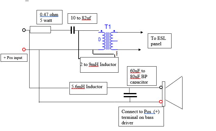
The panel is connected out of phase with the bass driver due to the 180-degree phase shift created by the second order crossover filter.
Doing this corrects for the phase shift, giving correct phase for both drivers. It’s important that the bass driver is in phase with the signal to ensure that bass frequencies are delivered correctly.
Note: An attenuation circuit as shown on the previous page will probably be necessary to match the output of the bass driver with that of the panel. The values will depend upon the driver being used and the DC resistance of the 5.6 mH inductor.
Using an Active Crossover
If an active crossover is to be used the 33uf on board capacitor should be removed by un-soldering it from the board and a wire link inserted in its place. The 0R47 ohm resistor should be left in place as it supresses a transformer / panel reactance that occurs in the higher frequencies.
It is essential that the active crossover does not feed frequencies lower than 150Hz and that a steep (12dB to 24dB / octave) roll off slope is used.
Attention must be paid to the phase of the signal delivered to the panels otherwise a hole in the response may occur around the crossover point.
Stacking Panels
The 505 panel has been modified to allow very easy stacking with minimal additional connections required.
When a second panel is placed on top of the first panel the connection pads underneath the edge channels will line up as shown below. It is simply a matter of making three bridge connectors to transfer charge from the lower panel to the top panel.
The audio feed is taken from the unfiltered supply from the central strip and requires the surface mount resistors to be in place on front and rear stators to filter the signal for the second panel.
The pads of the front of the panel do not have any wires connecting to them, this is done from the rear of the panel.
Above the end channels have been removed from the panels to expose the connection pads.
A simple bridge connector using plain or insulated wire is used to connect the 3 sections from the bottom panel to the screw connections on the top panel. The connection is made as shown.
Important
When soldering to the pads be very careful not to overheat them, use a hot iron quickly, do not linger on the pad as it may break free from the panel.
PCB stakes soldered into the pads can be used as a post to make a connection between panels.
An alternative way is to use the spare screw connection on each terminal block and take a second wire to the same connection on the panel above.
Another way is to install the lower panel upside down so that the terminal blocks are next to each other in the centre of the speaker. The connecting wires from the power supply are taken up and connected as normal to the lower panel, a short bridging wire is then taken diagonally to connect the V Pol and Front stators correctly. The rear stator connection is taken straight from the lower panel to the upper one.
There are a number of ways connection can be made but if you have any queries please contact us on
Remember to slot the end channels where necessary with side cutters to allow the links to emerge from the panel and replace them.
A single power supply will power 2 stacked panels without any problems, adding a third panel will cause a slight high frequency roll-off. Adding a fourth panel will cause more severe HF roll-off.
If more than 2 panels are required to be stacked in a single column driven by one power supply, we recommend a larger transformer be used to avoid HF roll-off and overloading the transformer.
Making a panel mount and combined Bass Box
The drawing below shows the type of box and panel mount we used in the prototype hybrid speakers:

The box does not have to be trapezoidal; it can be a simple box with 90 degree corners as long as the internal volume is kept to 15 litres. The asymmetric trapezoidal shape was chosen to reduce internal reflections and standing waves. If the back plate is parallel to the front baffle, use triangular wooden strips glued to the inner surface to break up the sound wave. Allow extra volume in the box to make up for the displacement caused by these strips.
Use a light fill of internal wadding, the amount required to suit your ears and room may need to be determined empirically (trial and error).
This layout can easily be extended to allow 2 stacked panels to be mounted for greater output. If stacked panels are used the network comprising a 3 ohm and 15 ohm resistor shown on page 17 will not be required. This network provides some attenuation of the bass driver to match a single panel, increasing panel overall size and output means this network is no longer necessary.