 ESL IV Description
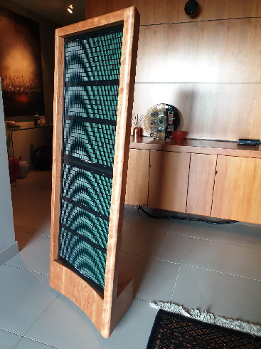
The ESL IV electrostatic loudspeaker is made up of 2 panels, approx. 600 x 450 x 14 mm (H x W x D), per loudspeaker, stacked vertically giving a 1200 x 450 mm array. It is permissible to stack further panels to create a larger array for very large rooms. A 1200mm high array (2x panels per speaker) is adequate for most domestic applications but 3 or even 4 panels may be stacked for very large rooms.
The front and rear stators are divided into 35 vertical conductive sections. Full range signal is delivered to the central strip and then to adjacent strips via a transmission line of SMD (surface mount device) resistors. The transmission line provides a high frequency filter action with each step creating equalisation to compensate for front to rear cancellation effects (typical of dipole speakers) and to provide a narrow source for high frequencies, this improves the dispersion characteristics.
The panel has 3 active sections, the top and bottom with 3 central pillars and the centre section with 2 pillars. The central section is a different width to top and bottom sections to provide a different resonance, thereby reducing the resonant peak that would otherwise be created. The whole area of the diaphragm reproduces low frequencies.
The stators are designed to mirror image with each other and are assembled with the resistive transmission line along the top of the panel on the rear stator. This places the 2 transmission lines at opposite ends of the panel where they cannot arc across the gap to each other. The printed lettering on the rear stator is therefore upside down while the lettering on the front stator is the correct way up. The inverted lettering on the rear is trivial as it will be covered by grille cloth.
When the 2 stators are assembled face to face there is a small channel created at the top and bottom of the completed panel. This channel us used to hide the connection wires that connect stacked panels together. A plastic H section is used to clamp and join the panels where they meet. This will provide a neat appearance from the front with no connections visible or accessible. The rear of the panels has the connecting wires which will be covered from view by grille cloth. The ends of the bottom and top panels have a plastic channel section clamping the panel together and covering the panel ends. The bottom end channel rear face has a cut-out for the connecting cables, the top channel has no cut-out as there are no further panels to connect to.
The central segment of all panels has a surface pad to allow connection to the power supply and to the next panel in the stack. When full range signal is applied to the central strip the unaltered signal is passed to the following panels in the stack where it propagates across the transmission line on each panel.
In a stacked pair the bottom panel has 2 sets of wires, longer at the bottom and short at the top. The longer wires at the bottom connect directly to the power supply / transformer board. The short wires at the top of the panel are used to connect to the bottom wires of the next panel in the stack. The top panel has wires from the bottom only.
In the case of 3 panels being stacked, the middle panel is fitted with short wires at top and bottom allowing connection to the bottom and top panels.
Design Philosophy
The ESL IV Electrostatic Loudspeaker kit has been developed with the knowledge and experience gained over many years with our other successful electrostatic speakers, the Acorn, ESL III, ESL IIIb, and ELS 5.
While the ESL IV has been designed primarily for the home constructor, there have been no compromises made to performance or sound quality to achieve this aim.
Indeed, the performance of the ESL IV is up amongst the very best of the commercially available electrostatic loudspeakers, regardless of cost.
As the ESL IV is a modular design, it is a simple matter to use 2 or more panels to make up a speaker as large as required for the room. We would normally recommend a maximum of 3 panels per loudspeaker.
While the ESL IV has good bass response in its own right, a sub-woofer to cover from 16Hz to say 40Hz may be necessary for organ music or for the very low frequencies engineered into most movies to enhance the special effects.
The final requirement was for the design to be easily constructed at home with minimal equipment and no special jigs. This design goal has been met.
Transducer Layout
The stator is made from FR4 circuit board material and is 1.6mm thick, the surface finish is ENIG (gold plated) for a smooth distortion and corrosion free surface. The inside copper surface has been insulated with 2 layers of UV cure soldermask and the top surface has 2 layers of black soldermask for a good cosmetic finish.
Vertical air gap spacers are made from copper clad FR4 and are bonded to both vertical sides of each stator. The horizonal spacers are made from the same material but have no copper on the surface, these are pre-drilled to line up with the clamping holes in the stator.
The thickness of the spacers has been chosen to give the best excursion for low frequency reproduction combined with good sensitivity. While more economical materials are available (PVC etc), FR4 has been selected to ensure the spacers have the same coefficient of thermal expansion (CoTE) as the stator itself. This material also adds significant stiffness to the panel, this is especially important in the horizontal plane where there is no support provided by the enclosure.
The 8 central pillars are made from plastic and are bonded to the surface of the stator. These maintain the gap tolerance in the active sections and provide further stiffness by clamping the stators together to form a sandwich structure.
The stator is made to be mirror imaged when one is inverted and placed against the other stator, this way the resistive transmission line is at opposite ends of the panel making it impossible for the resistors to arc across the gap to each other. This also allows a single design to be used as both front and rear stators.
The diaphragm is tensioned and attached to the front stator. The rear stator has 2 charge rails made from copper foil extending up each side. Connection to the charge rail is made via the corner surface solder pads.
The vertically segmented design causes high frequencies to be reproduced by the narrow central strips but the whole of the panel area reproduces low frequencies. This arrangement gives extremely powerful bass reproduction.
As the narrow central strip is emitting the high frequencies, the sweet spot is wide with very good off axis performance. When correctly positioned in the room, the stereo image never collapses into one speaker, even when listening greatly off axis.
Given a good recording and equipment, the soundstage presented is three-dimensional with distinct separation between instruments. Width extending past the outer boundaries of the speakers is apparent on those recordings in which this effect has been engineered. Frequency response is extended and flat and, as the design is essentially crossover-less, there are no signal modifying (destroying) capacitors or inductors to shape it to be acceptable.
Load Presented
As with all E R Audio designs, it was considered essential to make this speaker a very low shunt capacitance design.
As an example, ESL panels, which have air gap spacers that are simply glued onto a conductive stator, may be easy and fast to build but there is a serious trade-off. The area of grid that has the spacer covering it is non productive - it cannot drive the diaphragm, BUT the amplifier is still driving the capacitance it presents.
This means that on one speaker the size of a 3 panel ESL IV array, there would be over 2500 square centimetres of panel doing no work at all, but still presenting a load to the amplifier. To get this into context, this represents a “dead” panel 1 metre long by 25 cm wide. This means that the speaker has to be significantly larger to achieve the same output. This increases the capacitance, which in turn requires a more complex transformer and a more powerful amplifier to drive it.
The method adopted in the ESL IV is for the conductive section of the stator to be etched away from the perimeter and between the horizontal sections where the spacers are bonded to the stator surface. This means that all of the conductive surface of the stator is contributing to the output with very little shunt capacitance being present.
Stator Damping
Not required, FR4 is acoustically inert and does not ring.
Diaphragm Material
We use 3.5um Dupont Mylar C in this project. The use of this film results in amazingly fast transient response and low-level detail retrieval. When auditioning this material in the ESL IV, most listeners will comment on the extra detail that they are hearing from familiar recordings, which they have not heard before from previous systems.
Tensioning the Diaphragm
Panels that are supplied with diaphragms already fitted have had the diaphragm film tensioned on a pneumatic tensioning table and the film has been heat treated prior to bonding it to the panel. A heat activated adhesive is used to bond the film to the stator in this process.
Those that have opted for a DIY kit will follow the instructions detailed in the construction manual supplied with the kit.
Tensioning the diaphragm is the area that causes most home constructors some concern but the technique we have developed has helped literally hundreds of constructors repair their commercially made electrostatic loudspeakers.
Over the past 25 years we have developed a technique to tension the film that does not rely on time wasting tensioning frames etc. Our method is simple and quick and gives reliable, repeatable results. This is not a heat shrink method (the film does not shrink appreciably when heated), which can have some unpredictable results.
All the builder needs to do is provide a smooth flat surface large enough to place the 600 x 450 mm ESL IV panel with about 100 mm clearance all around, glass is best, something like an old window or shower screen will work. The tensioning tool and all materials required to successfully and easily apply the diaphragms are provided in the ESL IV kit. Tensioning and applying the diaphragm to one panel takes about 30 to 40 minutes.
Conductive Coating
Due to demand from our customers, we have developed a low mass, clear conductive coating that replaces our Opaque material. This coating is not an ionic solution such as used in static dissipants and does not rely upon ambient moisture to make it conductive. It is humidity independent meaning that the weather will not affect its performance.
This coating has been extensively tested in both high humidity areas and the very dry areas of the Australian desert regions with excellent results.
The surface resistivity is in the order of 500 to 1000 megohms per square when fully cured. This means that charge migration will not occur, even at the lowest frequencies of interest.
This gives good bass performance and reliability without sacrificing sensitivity.
Charging the Diaphragm
The vertical air gap spacers in the ESL IV have a copper track appled to the surface to enable charge to be transferred from the spacer to the surface of the diaphragm. There are surface pads in each corner of the stator that are used to connect to the copper track and to the EHT supply or the next panel in the stack. The air gap is the same for all sections on the panel.
The ESL IV has a single sheet of film covering the three sections. The conductive coating is applied only where it is needed, in the active area of the three sections on each panel. The copper charge rail on both sides of the panel effectively applies charge from both sides to the conductive layer.
The copper charge rails are applied to the panel half that does not carry the diaphragm. When the two halves are brought together, the copper strip contacts the conductive coating and transfers charge onto it.
EHT Supplies
New EHT supplies have been developed for the ESL IV. This design uses a small switch-mode inverter, which drives a voltage multiplier stage.
The supply has a single output, which provides the voltage required for the ESL IV.
The EHT supply is driven by an adjustable regulated dc supply, which is powered by a standard 12 volts dc Plug Pak, this means that there are no mains potential or high voltage wires leading to the loudspeakers, just 12 volts dc and the normal speaker cables from your amplifier. The on-board regulator eliminates any variations in polarising voltage due to mains voltage fluctuation.
The polarising voltage is set by adjusting a 25 turn trim-pot to adjust the output, setting the voltage applied to the panels is a breeze. As high voltages are difficult to measure and require specialised equipment, we provide a low voltage setting that is easily measured with a normal volt meter. The low voltage is measured at the output of the on-board regulator before being transformed by the small inverter. The low voltage reading is directly proportional to the output of the high voltage supply.
Audio Transformers
The audio transformers we use are another proprietary design of 1:90 turns ratio. Two transformers are used in a parallel / series configuration to give a turns ratio of 1:180.
These are a multi section, interleaved design with a power handling capability of over 100 watts each.
Low distortion and faithful reproduction of signal sources such as square waves were a priority.
These transformers are specifically designed for electrostatic loudspeakers with very high voltages envisaged; a second priority was placed on internal insulation and high voltage enamel for the winding wire. The high turns ratio gives sufficient drive voltage, even from lower output amplifiers, without putting too high a demand on current.
However, amplifiers with good current capabilities are necessary for high sound pressure level listening.
Panel Protection
The EHT supply board is fitted with a series of MOV (metal oxide varistor) devices that are designed to capture unwanted high voltage transient peaks. The devices are essentially out of circuit until a predetermined threshold voltage is reached, once this voltage is reached the MOV’s start to conduct effectively shunting the voltage and protecting the panels. If a severe spike is experienced (such as when unplugging one of the line level RCA plugs while the amplifier is set at high volume) causing the MOV’s to fully clamp the voltage, this will appear as a short circuit to the amplifier.
The input to the audio transformers are each fitted with a 0R47 ohm, 5 watt resistor which will act like a fuse and go open circuit, protecting the transformers and the amplifier. Amplifiers fitted with some form of protection will activate it to protect the amplifier.
You may be concerned the addition of these devices across the terminals of the stators will impact sound quality. This is not the case for a couple of reasons. Under normal operation the VDR’s do not conduct any current so are invisible to the audio signal. The VDR devices do have some internal capacitance that would normally add to the load presented by the panel. However, a number of devices are used in series so the total capacitance of the devices, which would add to the load being “seen” by the amplifier, is reduced to an insignificant level.